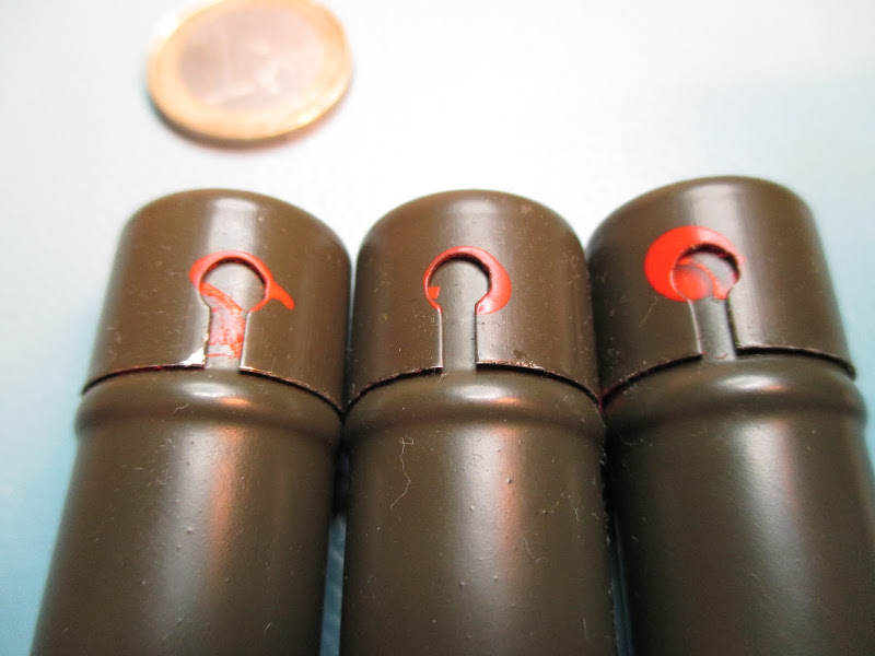
DP-70 dosimeter

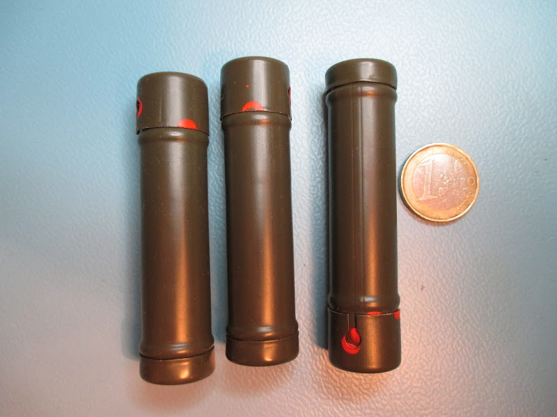
DP-70 was a chemical dosimeter used in the Polish army during the Cold War. A dosimeter is a device used to measure the amount of radioactive radiation absorbed by a body, in this case, by soldiers.

DP-70 dosimeter

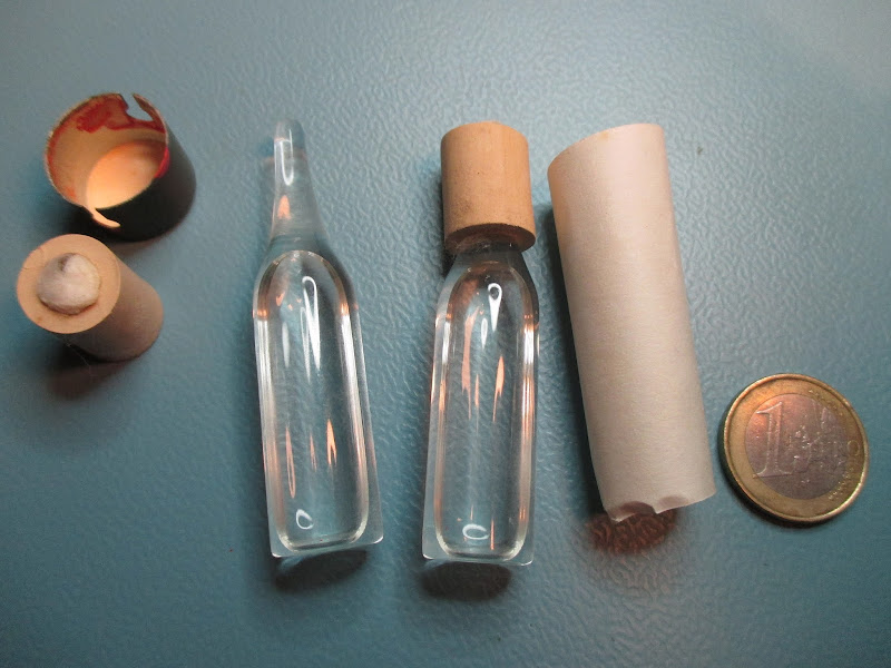
DP-70 has a form of a small metal cylinder (to protect the device in hard, combat conditions) that covers an ampule with a transparent liquid. This substance change color proportionally to absorbed radioactive radiation.

DP-70 dosimeter

It's a simple device, but has two major drawbacks - it can't be used by colorblind persons and is not precise. Due to those two factors, the device was replaced by more modern DKP-50 dosimeter.

DP-70 dosimeter DP-70 dosimeter DP-70 dosimeter

It can be bought for around two euro, unfortunately it's designed to measure ranges present during nuclear war, so it's far too insensitive to make any experiments with environmental radioactivity.

Extracting potassium (with its radioisotope) from cigarette ashes

Organisms are built mainly of carbon, hydrogen and oxygen, but they use many more chemical elements, one of them is potassium. After burning of organic matter, potassium stays in ashes as oxide that later is transformed to hydroxide. In the environment, potassium exists in a mixture of three isotopes: 93.3% of 39 K, 6,7% of 41 K, and 0,012% of radioisotope 40 K. The amount of mentioned 40 K radioisotope is really tinny, but sufficient to be detected using home methods.

In this post I will present a simple method to extract potassium compounds from ashes. Purity of the end product is low, from what I found online, for wood ashes, it's around 20-30%.

What is needed? Cigarette ash (for this experiment I used remains of 192 cigarettes - I'm a smoker!), water (can be tap water), stove, pot, two beakers (or jars), funnel, cotton, stirrer (or spoon). The whole process takes a couple of hours.

I've started from removing cigarette buts, matches, and other junks, the result was ~130ml of ashes.

Breadboard made from scrap electronics

A simple but useful breadboard can be made at home, it will be more expensive than those on the markets, but it's possible to add commonly used elements, like LEDs, switches, etc.

I hadn't had female sockets, so I cut in half old DIP-18 sockets - it works OK.

The bottom layer was coated with Lichtenberg's alloy - it's an easy and elegant way to protect traces from dust, humidity or oxidation.

The circuit looks like a monster, but there isn't a lot of logic - only sockets, and a couple of LEDs - I didn't want to add more components, at least in this version.

You can download Eagle files for this project from by GitHub.

USB li-ion battery charger

Li-ion cells become more and more popular due to their capacity and reasonable prices. In this entry I will show how to build a simple li-ion battery charger based on MCP73831 chip. It's a quite useful device for DYI projects,in addition its cost is only around 1,5 euro.

The device uses USB port as a power supply (mini-USB connector). I use the standard gold-pins as an output socket. There're three of them, but only two are used (looking on the image, counting from top: V+, V-). I will design my li-ion based devices in the same way (same socket, but female), then if I will connect it in the incorrect direction (rotated 180 degrees) they won't be damaged (V- connected to V-, but V+ connected to n/c pin) - simple way to avoid plugging in an incorrect way.

LED indicates if battery charging is in progress.

Pay attention to connection polarity, li-ion batteries can burn or explode if connected incorrectly. Never leave battery unattended while charging is in progress.

The PCB could be smaller, but it's made in this shape according to chip's documentation, additional copper space is used to dispatch heat produced during charging. The documentation mentioned 2-side layout, but I used only one side. The copper was coated by using Lichtenberg's alloy, so heat dispersion is improved - it seems that it's enough.

Eagle files can be downloaded from my GitHub.

That's all, I will use this for my . I will also have to thing about some DC/DC converter for them (to obtain 5V from li-ion battery), but that's a different story.

Yet another way protect pictures against copying

It's not possible to protect an image against any person, but it can be protected enough for most of the users. There are a couple of ways to do this, most popular are CSS tricks, but today I will present another way.

Can you save below image? I bet you can't! ;-)

Dangling else problem

What is a dangling else problem? It's presented below - what will print this program?

#include <iostream>

int main()
{
    bool a = true;
    bool b = false;
    
    if(a)
        if (b)
            std::cout << "foo" << std::endl;
    else
        std::cout << "bar" << std::endl;

   return 0;
}

It may seem that it won't print anything, but isn't true - on the screen we will see "bar". That's because the "else" is bound to the last "if" statement that wasn't already bound to other "else".

This may lead to bugs and confusion. One easy way is to always embrace body of the "if" statement in brackets. If we want to bind the "else" to the first "if" then correct parenthesis should be added as below:

    if(a)
    {
        if (b)
        {
            std::cout << "foo" << std::endl;
        }
    }
    else
    {
        std::cout << "bar" << std::endl;
    }

If we want to bound it to the second "if", it should be:

    if(a)
    {
        if (b)
        {
            std::cout << "foo" << std::endl;
        }
        else
        {
            std::cout << "bar" << std::endl;
        }
    }

What is good is that compilers will usually produce a warning in places where this error may exist:

 In function 'int main()':
8:7: warning: suggest explicit braces to avoid ambiguous 'else' [-Wparentheses]

Tiny and cheap lab generator

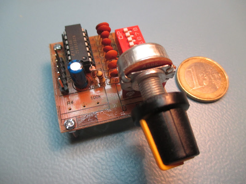
Function generator is a rely useful tool in the lab, a simple version can be build at home, there's a lot of examples on the Internet, some are much more complex and powerful, but this one is intended to be really simple and cheap. It can be also built-in in some bigger projects that also requires a generator.

The generator can output (only) square signal with adjusted frequency and pulse width. The amplitude may be also modified by soldering different values on the voltage divider on the output, it's a bit laborious, but if it will be used in digital or microprocessor projects, then there isn't really need for amplitude adjustment.

simple laboratory generator, front view

The generator is built from two NAND gates (IC1A, IC1B), that's a classic configuration used in many other circuits. S1 and C1-C8 selects the frequency, there is an equitation for it, but the general rule is that the more capacity thy have, the lower frequency is generated. By adjusting witch one switch are set to ON state, we can select plugged capacitors and the output frequency. R2-R4, D1, D2 changes pulse width.

IC1C, IC1D make a buffer. Old trick.

A voltage divider R5+R6 can be used to reduce an amplitude of the signal.

simple laboratory generator, circuit

Single layer PCB was used, some of the elements are SMD, but majority is THT.

simple laboratory generator, bottom view

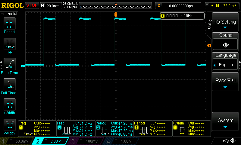
On the o'scope it's visible, that the signal looks good, below images show the lowest and highest frequency signal that can be generated, but it could be expanded by using smaller/bigger C1-C8 and R2-R4.

simple laboratory generator, oscilloscope view, lowest frequency simple laboratory generator, oscilloscope view, highest frequency

Project was created in Eagle, you can download all of its files (including PCB images for home made etching) from my GitHub. Image of top side needs to be mirrored before printing.

More readable way of casting primitive types in C++

How to cast a variable of one primitive type to another? Usually people use static_cast operator, but it can be done in other, more readable way.

Below example demonstrate the problem, and two solutions:

char var1 = 3;
char var2 = 5;

// first way
int result1 = static_cast<int>(var1 + var2);

// second way
int result2 = int(var1 + var2);

The same trick may be used e.g. when passing to a function an argument of different type that expected.

There is also C-style casting available in C++, but I didn't mention it above because it's discouraged.

Yes, I know, casting from one type to another is a common source of bugs, and can signify that overall design could be improved. That's true, but sometimes it's inevitable.

A trip with Geiger Counter on the Śnieżka mountain

During the Second World War Nazis established a uranium mine in Krkonoše mountains. Extracted ore was used in a research facility in Oranienburg. After the war, the mine was in polish borders, but Poland was then a puppy country of the USSR, so the ore was still extracted, but now was transported to the USSR. Later the mine was used in civil research.

I've visited those mountains with my Geiger counter, not the mine, but still close - Śnieżka mountain.

My construction uses three GM tubes instead of one - that's why the amount of pulses per period of time is also three times bigger. Don't panic! :) In addition, even if radioactivity is a bit bigger that in (for example) my home in Wroclaw, it's still not hazardous for health.

As a reference, at home my Geiger Counter shows around 60 pulses per minute.

As you will see below results were bigger than those that I observe at home, is it due to the uranium ore that is near? Maybe, I'm not sure, I wasn't on any other mountains with my counter, so I can't verify it.

Preparations

32F429IDISCOVERY board is used to count pulses and show results, it requires 5V power supply, the same as my Geiger Counter. Both were supplied from DC/DC converter (the cheapest I could buy), and 3xAA NiCd batteries. In total 250-300mA was drained from the batteries.

Final adjustments of the latest HW version - as usual, I made mistakes during the design of the PCB.

Geiger Counter - last modification before a trip

ATtiny44 evaluation board for DYI robots

Intro

I will start from saying that the board could be replaced by any Arduino plus some(s) its motor driver shield(s). So why I made it you may ask? Well, while I made this tiny tank-robot model presented on below pictures, I wanted to make at least some things by myself, and decide what I need and how I need it instead of only buying prefabricated stuff.

This is the result, hope you will enjoy it and that maybe you will find inspirations for your own stuff.

Her's what it has and what it can..

  • Handle two separate motors, each can run either "forward", "backward", or stop.
  • Motors can be powered from a separate power source (there's a jumper for that, if removed, power is taken from a source connected to a separate goldpin)
  • ATtiny24 manages the board, it's relatively small microprocessor, but I think that it will be fine for such project. All its pins are available via goldpins, I also added a couple goldpins connected to Vcc and GND to make easier connection to other boards, shields and stuff like that.
  • To make programming easier, 6 PINs ISP socket for the ATtiny24 is also included.
  • ATtiny24 can be removed and the motor driver can be managed from external source, e.g. an Arduino. This could be useful in future if the ATtiny24 would not be sufficient.
  • There isn't any voltage regulator, or step/up/down/ converter because it would make the board less flexible.

Circuit

The circuit is simple, consists only of a small microprocessor, motor driver, some filtering capacitors and a lot off connectors.

The hardware was designed in Eagle, the board is available on GitHub.

Software

PB0, PB1, PB2 and PB3 ports of the ATtiny24 are used to drive the motor, others are available for other purposes, e.g to communicate with the sensors. There's not a lot of them left, because the microprocessor is quite small, but I think that for such project, it will be enough.

DKP-50 dosimeter (radioactivity detector) tear-down

DKP-50 was a dosimeter produced for the Polish People's Army during the cold war era. It indicates amount of radioactivity absorbed by the body, a soldier was equipped in this device in case of nuclear conflict. A scale has range of 0-50R (R = Roentgen, a legacy unit of exposure of X-rays and gamma rays). 500R in 5h is usually lethal.

It's based on ionizing chamber that changes radioactivity radiation to an electric current, current discharges a capacitor that is also used as a power source. The device measures discharge of a capacitor over time. This is done by using a wire that accordingly changes its position and optic unit to make those results available for the operator.

If you're interested in radioactivity, you may also want to read about a Geiger–Müller Counter that I've made.

Sample result is visible on the picture. Note that it's inaccurate because the device was discharged and wasn't calibrated.

The deice, visible a plastic cap (with seal) to protect charging electrodes and a metal clip to attach the device to an uniform. On the cap, there're two names: "DKP-50" and "12".

Kirlian photography - electronic engineering meets parapsychology

Kirlian photography is an interesting photographic technique of capturing corona discharge of objects. The images basically contain only edges in a form of blue glow. Note: one of those photos is visible in "The X files" intro - read the whole article to know why!

In this post I will present my minimalist approach with common materials and without complicated construction. The results aren't that good as with more complex setups, but I think that they are still really interesting.

Materials

  • A camera with modifiable ISO and exposure time.
  • 10-30kV high voltage supply.
  • Tin foil. I used a foil in a form of adhesive strips because it's easier to stick it to surfaces, but a regular one can be also used.
  • Small piece of glass.
  • Slats or other things to put everything in place.

High voltage supply (10-30kV) made from CRT television flyback transformer

Old CRT monitor or TV is a great source of electronic components that can be used in DYI constructions. One of them is a flyback transformer that can provide 10-30kV output. The input voltage can be in a range from a couple of volts to over a dozen of volts, power consumption is a couple of watts. In my construction input voltage is 9V, power consumption is 5W.

A flyback transformer is driven by one or two transistors that should be also extracted from the same TV or monitor, those are high voltage transistors, that are hard to substitute and if bought separably can be expensive.

Modular DIY Geiger–Müller counter

The Geiger–Müller counter is a relatively simple tool to measure ionizing radiation. To increase sensitivity, construction presented here contains three (instead of one as usually) soviet STS-5 lamps. This is important for measurements of natural sources of (low) radiation like soil, rocks (an article about my trip with Geiger–Müller counter on Śnieżka mountain).

Principle of operation of a Geiger–Müller counter

When high voltage (typically 380-420V) is applied to the Geiger–Müller tube, the tube doesn't conducts electricity, but it does conducts for a short period, when radiation particle is observed. Those pulses are observed by the detector. The level of ionizing radiation is proportional to the amount of pulses detected in a constant interval of time (typically from 20s to 2,5min).

Geiger–Müller tube behavior can be described as a "button", that is "pushed" by an ionizing particle.

Homemade Geiger–Müller simplified circuit

Let's go further into the details. Geiger–Müller tube is made of two electrodes, ionizing particle creates a spark gap between them, to reduce amount of current that flows in this situation, a resistor is put in series with the tube. Marked as R1 on above circuit, R6 on below. Typically it's in a range 1-10M, acceptable values are listed in documentation of the GM tube.

There are a different ways to obtain a signal from the tube, in presented here, a resistor is connected in series between the tube and ground, changes of the voltage on the resistor are measured by the detector. This resistor is marked as R2 on above diagram, R7 on below. Typically it's in a range 10-220k.

Similarly to diode, a Geiger–Müller tube has its polarity, when connected in the opposite direction it will work incorrectly.

Below is shown a signal from GM tube when a particle is detected.

The electronic circuit of a Geiger–Müller counter

MC34063 is a DC/DC converter used to produce required high voltage, one of it's advantage over a simple NE555 or similar generators in this circuit is that it can monitor the output voltage and adjusts parameters to make it stable (R3, R4, R5, C3).

IC1A, R8, R9 are used as a comparator to filter out noises and produce binary signal (low=no pulse at this moment, high=pulse is currently being observed). R10, R11, R12 and a bunch of transistors drives LED, a speaker and (as an option) external digital devices, e.g. Arduino, or other evaluation board.

Waring! The device uses high voltage and can lead to unpleasant shock, injury or death. Don't touch the PCB or tubes when power is on.

Deobfuscation JavaScript code - how to start?

The easiest way to obfuscate code is to remove white-spaces that are not necessary and to shorten the names of variables and functions. A couple of years ago a made this simple tool to parse such obfuscated JavaScript code.

An example how the code can look after obfuscation and before passing it to a more readable form is presented below.

(function(){var s=true,t=false,aa=window,u=undefined,v=Math,ba="push",fa="slice",ga="cookie",y="charAt",z="indexOf",A="gaGlobal",ha="getTime",ja="toString",B="window",D="length",E="document",F="split",G="location",ka="href",H="substring",I="join",L="toLowerCase";var la="_gat",ma="_gaq",na="4.8.6",oa="_gaUserPrefs",pa="ioo",M="&",N="=",O="__utma=",qa="__utmb=",ra="__utmc=",sa="__utmk=",ta="__utmv=",ua="__utmz=",va="__utmx=",wa="GASO=";var xa=function(){var j=this,h=[],k="ABCDEFGHIJKLMNOPQRSTUVWXYZabcdefghijklmnopqrstuvwxyz0123456789-_";j.uc=function(m){h[m]=s};j.Nb=function()

[...]

After parsing it to more friendly form, we can spot functions, variables, loops and other things. Although the code still is far from being beautiful, it looks much better.

(function()
{
 var s = true,t = false,aa = window,u = undefined,v = Math,ba = "push",fa = "slice",ga = "cookie",y = "charAt",z = "indexOf",A = "gaGlobal",ha = "getTime",ja = "toString",B = "window",D = "length",E = "document",F = "split",G = "location",ka = "href",H = "substring",I = "join",L = "toLowerCase";
 var la = "_gat",ma = "_gaq",na = "4.8.6",oa = "_gaUserPrefs",pa = "ioo",M = "&",N = " = ",O = "__utma = ",qa = "__utmb = ",ra = "__utmc = ",sa = "__utmk = ",ta = "__utmv = ",ua = "__utmz = ",va = "__utmx = ",wa = "GASO = ";
 var xa = function()
 {
  var j = this,h = [],k = "ABCDEFGHIJKLMNOPQRSTUVWXYZabcdefghijklmnopqrstuvwxyz0123456789-_";
  j.uc = function(m)
  {
   h[m] = s
   }
  ;
  j.Nb = function()
  {
   for(var m = [],i = 0;
   i<h[D];
   i++)if(h[i])m[v.floor(i/6)]^ = 1<<i%6;
   for(i = 0;
   i<m[D];
   i++)m[i] = k[y](m[i]||0);
   return m[I]("")
   }
  
  }
 ,ya = new xa;
 function Q(j)
 {
  ya.uc(j)
  }
 ;
       [...] 
USB powered thermometer with an interesting data display

Almost each person interested in building electronic devices has built at least one thermometer and power supply in his life. I'm not different, to add to this, today I will present one of my thermometers.

Original concept was different, I wanted to use it as a weather station, wake up, go to my balcony, smoke a cigarette and check what on this device what is the temperature, humidity and air pressure. At the end I decided to build a small thermometer (in future with all mentioned features), that I could plug to my computer and check conditions in my home.

What is nice here is that the data is displayed original way, there are two rows of nine LEDs, if on the upper row second diode is on, and on the bottom row fifth diode is on, then the value presented by the device is 2*10 + 5 = 25. It can sounds complicated at first, but in practice it's fast and intuitive. Below is an example, value presented on the display is 25:

Popularne pytania z rozmów wstępnych dla programisty C/C++

W tym wpisie podzielę się zbiorem pytań, które często powtarzają się na różnych rozmowach wstępnych na stanowisko programisty C/C++. Są to pytania techniczne - nie opisałem tu żadnych pytań miękkich (HR'owych). Spotkałem się z nimi sam (już prawie 10 lat pracy, jak ten czas leci..), a niektóre zadawałem osobiście, gdy byłem po drugiej stronie stołu. Mam nadzieję, że taka lista okaże się pomocna podczas przygotowań do rozmowy.

Na początek pytania związane stricte z C/C++. Kolejność losowa.

  • Czym jest język obiektowy? Czy C++ jest językiem obiektowym (odpowiedź na to, czy jest może się różnić w zależności od tego, jak definiujemy język obiektowy)?
  • Napisz program, który jest poprawny składniowo w C, a nie jest w C++.
  • Czym są słowa kluczowe (w kontekście zmiennej, w kontekście metody) static i const? Co oznacza słowo kluczowe volatile?
  • Czym różni się alokacja pamięci na stosie od alokacji pamięci na stercie? Jak zmienną na oba sposoby? Kiedy stosować jedno, a kiedy drugie?
  • Czym jest smart pointer? Kiedy go stosować? Jakie są rodzaje?