The Geiger–Müller counter is a relatively simple tool to measure ionizing radiation. To increase sensitivity, construction presented here contains three (instead of one as usually) soviet STS-5 lamps. This is important for measurements of natural sources of (low) radiation like soil, rocks (an article about my trip with Geiger–Müller counter on Śnieżka mountain).

Principle of operation of a Geiger–Müller counter
When high voltage (typically 380-420V) is applied to the Geiger–Müller tube, the tube doesn't conducts electricity, but it does conducts for a short period, when radiation particle is observed. Those pulses are observed by the detector. The level of ionizing radiation is proportional to the amount of pulses detected in a constant interval of time (typically from 20s to 2,5min).
Geiger–Müller tube behavior can be described as a "button", that is "pushed" by an ionizing particle.

Let's go further into the details. Geiger–Müller tube is made of two electrodes, ionizing particle creates a spark gap between them, to reduce amount of current that flows in this situation, a resistor is put in series with the tube. Marked as R1 on above circuit, R6 on below. Typically it's in a range 1-10M, acceptable values are listed in documentation of the GM tube.
There are a different ways to obtain a signal from the tube, in presented here, a resistor is connected in series between the tube and ground, changes of the voltage on the resistor are measured by the detector. This resistor is marked as R2 on above diagram, R7 on below. Typically it's in a range 10-220k.
Similarly to diode, a Geiger–Müller tube has its polarity, when connected in the opposite direction it will work incorrectly.
Below is shown a signal from GM tube when a particle is detected.

The electronic circuit of a Geiger–Müller counter
MC34063 is a DC/DC converter used to produce required high voltage, one of it's advantage over a simple NE555 or similar generators in this circuit is that it can monitor the output voltage and adjusts parameters to make it stable (R3, R4, R5, C3).
IC1A, R8, R9 are used as a comparator to filter out noises and produce binary signal (low=no pulse at this moment, high=pulse is currently being observed). R10, R11, R12 and a bunch of transistors drives LED, a speaker and (as an option) external digital devices, e.g. Arduino, or other evaluation board.
Waring! The device uses high voltage and can lead to unpleasant shock, injury or death. Don't touch the PCB or tubes when power is on.

Open image in a new tab to see it in full resolution.
Vcc=5V, current consumption=30mA.
First running and troubleshooting
The voltage on C4 should be in an acceptable range for used GM tube. It's usually is around 400V - be careful during measurements! If the voltage is out of range, then C1 (frequency of DC/DC converter), C3, R3, R4, R5 (feedback voltage of the DC/DC converter) can be adjusted.
Next thing is presence or absence of pulses on R7. If there's no pulses as presented on above picture then verify if the GM tube is plugged according to its polarity.
If pulses on R6 are visible, but IC1A output doesn't change, then R8, R9 should be modified, they set the threshold when signal signal from R6 should be interpreted as low or as high.
Hardware prototype
The PCB uses THT and SMD components, but nothing that can't be done without hot-air station. It has one layer.
The project was modeled using Eagle, all files can be downloaded from my GitHub.
Software
As visible on the pictures, I've used 32F429IDISCOVERY board to count pulses and to visualize results.
The project was made in CooCox IDE and was built on top of the libraries from stm32f429 repository made by MaJerle.
The firmware can be downloaded from my GitHub, from the same repository where hardware model is stored.
Experimenting
Thorium decay creates α particles that can be detected by Geiger–Müller counter. A common source of this chemical element are red welding electrodes, they contains 2% of 232 90 Th isotope.

Change of frequency of pulses can be easily observed when electrodes are placed near to the tubes.
Experimenting - more ideas
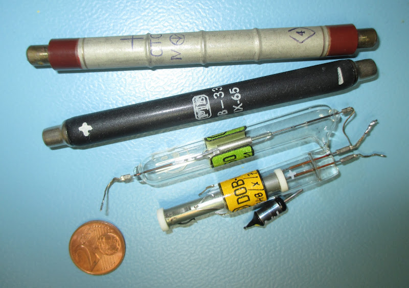
The circuit presented above can be adjusted to operate with other Geiger tubes (they vary in required voltage). I bought a couple of Geiger tubes to check their sensitivity, they were manufactured in Poland and in Soviet Union. From up: STS-5, BOB-33, DOB-50, DOB-80 (with broken glass), DOI-30.
I have in plans building my home radiometric station (it would be part of part of a weather station) connected to the web, so I get the data wherever I am.
Articles about similar constructions of Geiger–Müller counters
- DIY/Homemade Geiger Muller Digital Counter V3
- Pocket radioactivity detector
- The Geiger counter
- Geiger-Muller Tubes
- Geiger Müller counter
- MicroGeiger
That's a lot of useful information, thanks.
ReplyDeletePretty amazing!
ReplyDeleteThanks.
DeleteHi,
ReplyDeleteI'm planing to build similar thing, and have couple of questions.
1. What's the difference between those tubes? Do they detect different particles (alpha, beta, gamma)?
3. What's the sensitivity?
4. Is the voltage same for each type of tube?
5. Where did you bought them?
Thanks for any info.
>1. What's the difference between those tubes? Do they detect different particles (alpha, beta, gamma)?
DeleteThat's a hard question, some of the information you can get from here:
http://www.dozymetry.8p.pl/index.php/liczniki-geigera
>3. What's the sensitivity?
To check that I would have to add pulse counter to this construction and measure amount of pulses per one or two minutes. IMHO it's hard to answer to your question without that. BTW I have in plansadding this thing (based on STM32 Discover), so we will know.
>4. Is the voltage same for each type of tube?
You mean the HV? No, but the range is relatively small (350V-450V), so one construction can be used with many kind of tubes.
>5. Where did you bought them?
On polish auction portal (allegro), but there's a lot of them also on eBay.
Hi.
ReplyDeleteThanks for your schematics. I think it is very interesting to have used a 34063.
I have just one simple question: what type (and value) of inductor have you used?
Thanks for your feedback.
Hi,
Deletethanks.
The coil is 680µH, 800mA, 1.49Ω.
From: http://www.tme.eu/en/details/coil0810-0.68/vertical-mounting-tht-inductors/ferrocore/
-Robert
What does "down" and "up" buttons does?
ReplyDeleteI assume, you're talking about the Arduino shield, Am I right? If not, please fix me.
DeleteOne of them is not used, one is selecting current layout:
- one minute per bar bargraph
- histogram in above mode
- one hour per bar bargraph
- histogram in above mode
The reason why there're two buttons is because in future more complicated interaction with user may be wanted and it's better to have two buttons instead of just one. This eliminates need to make a new HW revision of the board.
BTW I've recently commited a new, fixed version of this board but I didn't make it yet.
You will find more details here:
Deletehttps://robertgawron.blogspot.com/2016/07/using-arduino-to-process-data-from_24.html
Thanks!
DeleteI have some questions about circuit:
ReplyDelete1. What resistance values R9 and R14 should have?
2. What R1 resistor does? It is used as a fuse here?
3. Can I use simple buzzer with generator instead of 8ohm speaker (with additional resistor)? Do you think it will work? ;)
4. Can You explain what L1 does in this circuit?
Thanks
Those are good questions :-)
Delete>1. What resistance values R9 and R14 should have?
R8 and R9 creates voltage divider, you want this constant voltage to have the same value as the voltage from the input when you want to trigger state on/off.
R14 - while this is relatively slow signal, I would go for 1k.
>2. What R1 resistor does? It is used as a fuse here?
R1 - it's a faulty design, L1 should be connected to it, in a form as on the circuit it just make useless over-current protection of the chip.
>3. Can I use simple buzzer with generator instead of 8ohm speaker (with additional resistor)? Do you think it will work? ;)
I think that yes, but you would like to check this by providing the buzzer power on long as the pulse, might work, might not, depends on the internal circuit of the buzzer.
>4. Can You explain what L1 does in this circuit?
Now that's complicated, but I like the simple explanation (that's not perfectly ok, but still)
[input] voltage x current = [output] voltage x current
If you load the input stage with a lot of current and small voltage, you can get a lot of voltage and small current. This is crude and not the best explanation, but shows great what's going on here.
>simple buzzer with generator instead of 8ohm speaker (with additional resistor)?
DeleteWhat resistor?
>[input] voltage x current = [output] voltage x current
DeleteBy "[output] voltage x current" I mean max current.