Nuclear-radiation detection using very simple ionization chamber and a single J-FET transistor

Today I will show a very simple ionization chamber that can detect radioactivity. I was able to detect with it ionizing radiation from a smoke detector (Am241 isotope). It's also immune to electromagnetic interference (EMI) due to a good shielding.

This device doesn't explicitly use any power supply. It's connected to a multimeter set to measure resistance, in this mode, the multimeter provides a small voltage to its probes (R=I/U, so to measure resistance, it has to put voltage across measured element). This is sufficient here, because basically we just need to polarise electrodes of the ionization chamber and nothing more. My multimeter provides 5.6V in this mode.

My setup is presented below, note that the sensor is this metal box, not the PCB visible on the image.

The chamber is made from copper plate soldered carefully to prevent any holes where electromagnetic fields could flow and disturb readings. Inside is one BF256B (n-channel J-FET) transistor, its gate is connected to one of ionization chamber plate made from a leg of a THT resistor, source pin is available externally, this is where "plus" probe of the DMM is connected, drain is connected to the metal case (that is both and electrode and is shielded against EMI).

ionization chamber circuit

I've used Keysight 34460A as a multimeter here, because it has histogram mode, that will be useful to look if the measured value is stable over time. PLC was set to 0.2, it will reduce accuracy, but will give much more samples.

Below two images present what is inside of the sensor (only JFET, as mentioned above) and the sensor mounted. The front was shielded using tin foil, that was secured tightly by insulation tape.

There are many movies on YouTube with people constructing ionization chambers, however, those aren't shielded completely and due to high wideband gain in those circuits, they will pick-up any electromagnetic radiation, so the results aren't very useful.

Those designs measures not only ionizing radiation, but also whole electromagnetic spectrum. Here I tried as a dummy test to place the a metal object to check if the measured value won't change, without a shielding it would probably be a big peak.

Time to show results. The resistance decreases when the amount of ionizing radiation increases, below you can see two peaks on the histogram, one on the left is when the sample (Am241 isotope) is present next to the sensor, on the right, when there is no sample.

ionization chamber results

I think, that it's a very interesting circuit, and can be used for example to understand how different shielding prevents radioactive radiation, etc. It's limited, but a good start to making own ionizing chambers.

Nuclear physic applied in smoke detectors

Not many people know, but in some smoke detectors, radioactive materials play an essential role. Today I will present one of those devices, and my -successful- attempt to reverse engineer it and get the circuit diagram.

Those smoke detectors use a small amount of Americium-241 (chemical symbol: Am) obtained in nuclear reactors as a decay product of Plutonium-241. Am241 emits mainly alpha particles, but also some gamma rays. In smoke detectors it is in a form of an oxide Am02.

When alpha particles collide with atoms in the air, as a result, ions are produced. The amount of those ions is measured by smoke detector and is quite stable over time (Am241 has half-life of 432 years), however, when the smoke is present, smoke particles neutralise alpha particles, so the measured value drops. This drop is the signal of fire, so the smoke detectors start buzzer to alert people in the building.

To measure those ions (produced by ionizing radiation), ionization chamber is used. It has a form of two differently charged plates shaped and placed in such distance that the ionizing radiation can flow between them.

Those plates, when charged, create an electric field that attracts those ions. When they are collected by plates, and additional voltage is created between plates, this voltage can be measured. The bigger this additional voltage, the bigger is the ionizing radiation.

When those smoke detectors are used as designed, they don't pose a radioactive hazard, however, if those devices are disassembled, it must be done with great care. Alpha particle sources (as used here) are very dangerous if they came into the lungs in a form of dust. They are also dangerous if digested.

On below image, you can see the ionization chamber. It's connected in the air directly to the pin of the chip to avoid parasitic currents flowing on the PCB. This is because voltages created by ionization chambers are very low. Radioactive element is inside of the ring.

To be honest, I think that the PCB could be routed much better - angles of traces should be 45° if possible.

As was visible on previous pictures, ionization chamber is soldered directly above the chip that runs this device. I wanted to know what is this chip, but didn't want to solder off the ionization chamber, that's why I reverse engineered this PCB into electronic circuit and later found an online datasheet of the chip that fits here. My works are visible below.

After searching, I have found RE46C120 datasheet, so now I was pretty sure it's this chip. Just to be sure, I checked on the oscilloscope, what signal is on the TP3 and how it looks on the datasheet - it's the same.

That's basically all for today, I wanted to share with you the idea of those pretty interesting devices.

Semiconductor Nuclear-Radiation Sensor: Part I

Currently I'm trying to make a working version of a radioactivity detector that uses semiconductor as a sensor. It's a different approach than Geiger-Muller detectors or ionization chambers, more complicated, but also much more interesting.

While Geiger-Muller counters can only provide information about the amount of particles in a period of time, semiconductor detectors can also measure their energy, so it's possible to say much more about the nature of observed ionizing radiation. Some of the disadvantages of these detectors are that they are more expensive, complex and sensitivity may degrade over time.

The current version doesn't work, but I think it's so interesting concept that I've written this entry anyway.

semiconductor radioactivity detector

The idea is that when ionizing particle (alpha, beta or gamma) is blocked by the p-n junction, a small amount of the energy is released. It has a form of a current spike and can be observed by the next stages of the device.

The p-n junction is just a diode polarized reverse-biased. To make the working area of the p-n junction bigger, a photodiode is used. I know that there also exists specialized versions that are more sensitive, however, I couldn't find any in any online electronic shops.

In my design, the sensor is D1, it's polarized by R1, and C1, R2, L1 (those last three elements are making a low band filter to block noise from power supply, they should be as close to D1 as possible).

The first stage of an amplifier is based on a N-JFET to minimize current sink from the measured circuit, in addition, this type of transistors are extremely fast (that's why they are used widely in RF designs). To reduce parasitic currents between PCB traces, this part is mounted "in the air". EMI that could affect this stage are reduced by a small mass connected shield made from copper and aluminium tape.

Next two steps are high pass amplifiers. Since the signal is very small and those are not rail-to-rail opamps, a symmetrical power supply or virtual mass should be used. I've forgotten about that so lately I just used additional AA battery connected between negative power pin of the opamp and ground.

There are three outputs: raw, high/low (R10, R11, IC1C) and integrated over a period of time (IC1D, R12, R13, R14, C9, C10).

semiconductor radioactivity detector circuit

Below image shows the sensor, I've removed the protective glass from the photodiode to expose it better on the ionizing radiation.

The PCB looks like a nightmare because I've scratched some pads during multiple soldering and desoldering of elements, also some traces were cut and connected again, etc. It's a big blow of a mess now and I think that the story of this PCB is ended, soon I will design a new one based on the experience I've gained.

As I've said in the beginning of the article, the current version doesn't work - I can't observe anything except noise. This may be due to multiple problems. One of them is a proper shielding, tracks length, etc. It's a challenge to shield the device from EMI, but still make it sensitive to ionizing radiation.

Another problem is that I can test it only with alpha or beta particles, but they have big problems penetrating objects (are easily blocked), so it may be that they aren't even going to the pn junction, but are blocked by the case. This is something that is unclear to me at this moment.

I will continue working on this project and write a new article when I will make some progress.

Using Arduino to process data from Geiger–Müller counters

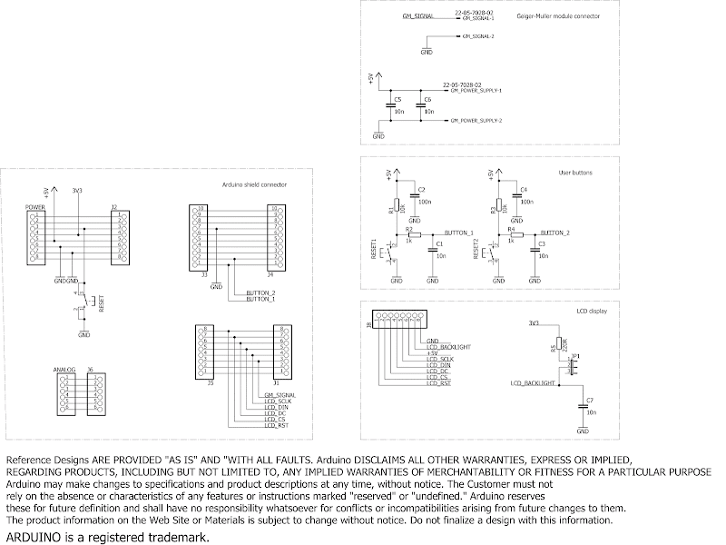
In the previous posts I've described a simple Geiger–Müller counter and various experiments with this device. Today I would like to present Arduino project to communicate with a Geiger-Muller counter, gather data and present it to the user. The device is based on Arduino Uno, Nokia 5110 LCD and homemade shield.

Currently it's possible to show two layouts: bar graph of the pulses in one minute interval and histogram of the gathered data. Both graphs are auto-ranging in Y axis. On the top of the pulse graph is visible also a numeric value of the last sample. The length of the histogram data is 4 minutes, the amount of bins is calculated automatically.

Below is visible layout with pulses per quant of time and histogram of them. You can clearly observe Gaussian distribution on the second image.

Hardware

I didn't want to place all of the connections and input PCB dimensions of a shield, so I've used as a base one of freely available shields and modified it to my needs - I've left the licence disclaimer unmodified. Unfortunately, I wrongly connected LCD, that's why the LCD looks like rotated 180 degrees. Anyway, it still works and I don't plan to make a new PCB to fix it.

I tried to make the code reusable in my other projects so the structure may look overcomplicated, but I think it's as it should be.

Software

Followed 3rd party librairies needs to be installed, to install them in Arduino IDE go to sketch -> Include Library -> Manage Libraries then type library name and proceed with installation.

  • Adafruit-GFX-Library
  • Adafruit-PCD8544-Nokia-5110-LCD-library
The main component is the GMCounter class that collects data in a circular buffer. I wanted to pass as an argument a size of the buffer, but also wanted to avoid using dynamic memory, finally I made this parameter an argument of template class, so now creating an object of this class looks like:
 static GMCounter<4 * 24> hourGMCounter;

This will create an object with this class with a buffer for 4*24 samples. I think, that it's quite cool.

There's a lot of commented out code in the main function, it was used to test parts of the program as it was developed. I didn't remove it because it still can be used if I will add new features.

Download.

The source code and Eagle files of the project is available on the GitHub, feel free to download and try it if you're interested in this area of physic.

How to check how many elements an array has?

In C it's possible to omit typing array size if it's fields are provided immediately, so the compiler can easily calculate the size by itself. This is presented below, note empty [] parenthesis.

    char* sampleArray[] = {
        "Hello world!",
        "How are you?",
        "You like coffe?"
    };

We can also specify the size directly:

    char* sampleArray[2] = {
        "Hello world!",
        "How are you?",
        "You like coffe?"
    };

Or use the best way:

    const int SampleArraySize = 2;

    char* sampleArray[SampleArraySize] = {
        "Hello world!",
        "How are you?",
        "You like coffe?"
    };

In the first two examples we don't have a variable that would tell us how many elements the array has. Sure, we may hardcode it, but it's not a good idea from a maintainability point of view.

We may calculate the size of above array by using a simple trick:

int sampleArrayLength = sizeof(sampleArray) / sizeof(sampleArray[0]);

Note that it will work with all built in types and if the size or even the type of an array will be changed in the future, this line will still be correct.

Below you may see a simple use case.

#include <stdio.h>


int main()
{
    char* sampleArray[] = {
        "Hello world!",
        "How are you?",
        "You like coffe?"
    };

    int sampleArrayLength = sizeof(sampleArray) / sizeof(sampleArray[0]);

    printf("someStrings array has %d  elments counting from one.\n", sampleArrayLength);

    for(int i = 0U; i < sampleArrayLength; i++)
    {
        printf("#%d element: %s\n", i, sampleArray[i]);
        
    }
    
    return 0;
}
sh-4.3$ main                                                                                                                                                                                                                                            
someStrings array has 3  elments counting from one.                                                                                                                                                                                                     
#0 element: Hello world!                                                                                                                                                                                                                                
#1 element: How are you?                                                                                                                                                                                                                                
#2 element: You like coffe?

Unfortunately, it will not work for arrays passed as pointers - for them, we need to pass size of an array as an additional argument.

How to check how many elements an enum has?

While C language doesn't offer build in method to check how many elements an enum has, it's still possible to obtain this information by using a simple trick.

The idea is to add a dummy element at the very end, since numeric enums values are 0, 1, 2, 3, 4, 5, ..., the numeric value of last element will be also the amount of elements that this enum has.

#include <stdio.h>

typedef enum Fruit {
    FRUIT_APPLE,
    FRUIT_ORANGE,
    FRUIT_BLACKBERRY,
    /* place new elements below */
    
    /* guard */
    FRUIT_LAST_ELEMENT
} Fruit;

int main()
{
    int fruitEnumLength = (FRUIT_LAST_ELEMENT - 1);
    printf("Fruit enum has %d elments counting from zero.\n", fruitEnumLength);

    return 0;
}
sh-4.3$ gcc -o main *.c                                                                                                                                                                                                                                 
sh-4.3$ main                                                                                                                                                                                                                                            
Fruit enum has 2 elments counting from zero.  

This technique may be useful for sanitizing input data or for writing tests.

Making your own PCB cleaner mixture

Commercial PCB washing solutions are relatively expensive, much cheaper and still powerful one can be prepared at home. It's based on trisodium phosphate, highly alkaline substance able to reduce oxides and react with grass forming soaps. Soaps in chemical meaning, not something we buy at store.

A sample PCB smashed into two pieces - on the left original state, on the right washed up.

DIY water based PCB solvent: before and after

Ingredients

The procedure is simple - a PCB is just placed into the solution and shaken from time to time to speed up the cleaning. Heating is not needed.

I'm using a cheap ultrasonic washing machine - I still don't know if it's working or if it's just a placebo and a bit of a noise, but it seems that at least it mix the water. I've placed the mixture into a glass and then placed it into the water in the washing machine. This is less efficient, but device is easier to clean after use.

DIY water based PCB solvent: ingredients

Note: trisodium phosphate is highly alkaline - it's visible on below below on below universal indicator. Use protective glasses and gloves.

In case of skin contact, wash the solution wash it with a lot of water. In case of a skin contact with the powdered substance whip it by using a rug and then wash it.

DIY water based PCB solvent: universal indicator

Trisodium phosphate was widely used till 70's, it's an inexpensive and effective cleaning agent, but is not environmental friendly.

Home-made mixture for chemical PCB tinning (alcaline bath)

Today I will present a method for PCB tinning that uses alkaline bath. What does alkaline bath mean? It says that the solution that we're using for tinning has this pH, in opposition acid bathes also exists - one of the example I presented in my previous post about PCB tinning at home.

This method is less expensive that the acid one, the results of both are comparable, but because of how a relatively dangerous alkaline bath is, I don't plan to use it. If you're searching a method to tin your PCBs, I would strongly suggest either using Lichtenberg's alloy (described here) or chemically tin them by using acid bath.

Ingredients:

Instead of pure metallic tin, a solder can be used, to increase its reactive surface, it can be melted on a small scrap of a laminate.

Note: NaOH is highly aggressive substance, it can easily permanently damage eyes or skin. Dissolution of an alcaline is strongly exothermic which means that water heats up, it can even start boiling and splashing dissolved NaOH!

Note: protective glasses and appropriate gloves should be used.

Note: don't use any containers, spoons or other small tools that you are also using for cooking, have a separate set for tinning.

PCB and tin (or mentioned above laminate) is placed in a high beaker. 100ml of water is added, then extremely slowly 1/2 teaspoon of NaOH and SnCl2 mixture is added. Mixture is heated (not boiled!) in heated bath similar to presented in this post. Tinning takes 10-20 minutes.

I haven't use polishing paste, so the surface isn't smooth and glossy, but technically it doesn't matter.

Solder wets surface very well, it's visible on below image.

To summarize, despite good results and low proce, I think that it's too dangerous to tin a PCB this way.

PCB tinning using Lichtenberg's alloy

The Lichtenberg's alloy is an interesting way of home PCB tinning - it's inexpensive and there is no need to polish cooper or use specialized tools and chemicals. The negative side is that the alloy is hard to obtain, fortunately it's not expensive. For some countries, it might not be possible at all to buy it.

The alloy contains 50% of bismuth, 30% of lead and 20% of tin, but what makes it interesting is that its melting point is 95-100°C. It means that it melts in boiling water - that's the idea if this technique.

Below you may see drops of The Lichtenberg's alloy.

We will need a couple of grams of the alloy, pan with lid, a tablespoon of citric acid, silicon spoon and old tweezers or similar tool.

  • Fill pan with tap water to 1/2 - 1/3 of volume, put inside the alloy and your PCB, cover the pan with lid to speed up heating.
  • When the water boils, use tweezers to immobilize the PCB - squeeze it to the pan. Dispatch alloy on whole copper surface by using a spoon. Put the lid again.
  • After a couple of minutes, immobilize the PCB again and by using a spoon, remove alloy excess from the PCB.
  • Clean the PCB in water, dry it by using a rag.

Citric acid is used here in two ways: as a flux and to decrease boiling temperature.

Note: don't use pans or spoons that you are also using for cooking, have a separate set for tinning. Please keep in mind that Lichtenberg's alloy contains lead, the method involves citric acid, a product of those (lead citrate) is (at least) unhealthy if digested.

Note: several similar alloys exists (e.g. Lipowitz's alloy), probably they could be also used, but always check theirs recipe. Especially make sure you don't use something that contains cadmium!

Note: don't spoil on your body any boiling water during above procedure.

Below is an example of a PCB tinned by using this method, it's a USB Li-Ion battery charger

If you liked this idea, you may also check the article about inexpensive chemical PCB tinning.

Home-made mixture for chemical PCB tinning (acid bath)

While it's possible to buy ready to use tinning formulas, making your own is much less expensive. Various recipes exist for tinning copper, today I will present a simple one that uses ingredients available at online chemical stores. It's one of acid bath methods.

Ingredients:

Simply put PCB into the solution and wait a couple of seconds, the more time the PCB is in the solution, the thicker a tin layer is. It's not needed to heat up the solution - room temperature is sufficient.

The substances are irritating, if you want to apply this method at home, please use gloves and store ingredients and mixture away from children.

The first PCB that I tinned this way is presented below. Solder wets the surface easily! Next time I will use polishing paste before tinning - this should help to obtain smooth and shiny surface.

Here is the device before testing it - it's a driver for a dosimeter based on DKP-50. Not the tidiest construction, but still looks nice.

In the next post I will present PCB tinning by using Lichtenberg alloy. You may also check related previous post about galvanic copper plating.

9V/1kV DC/DC converter

Currently I'm working on a device to electrocute home insects like cockroaches, progress is small because they are smarter than I thought, but that's a different story. For that project I had to find a source of sufficient high voltage and output power. Presented in previous post 5V/400V converter had insufficient voltage and power, another option, flyback transformer was too dangerous to be used here.

Finally, I have made a new high voltage supply based on an inverter transformer and voltage doubler. It seems to be ok for this job, but it can be used in various other applications so I'm presenting it in a separate entry.

Warning! the device produces high voltage that can be lethal, if you want to build it, please take cautions.

The transformer was salvaged from old LCD monitor, it was used there to power fluorescent tube. It costs around 6$, so they are not expensive. Unfortunately I couldn't find Eagle component library for it, so I had to make a new one. Q1 initially hasn't had a radiator, but later I added a small one because it was getting warm.

Full output voltage is present on R11, so it was protected against accidental touch by using a shrink tube. It's not the best way, but it's still better than nothing. All connectors have latches to avoid accidental slip out - important, especially for high voltage ones.

High voltage traces have bigger clearance to prevent spark gaps. Positive power supply rail has bigger width, because the current is around 330mA.

As visible on the rendering, by an accident I swapped top/bottom layer of two diodes. Opss!

A square generator is made from IC1A and IC1B, frequency depends on C1, R3, R4, pulse width depends on an R3 and R4 ratio. The signal is buffered by using IC1C and IC1D. Voltage doubler is made from C9, C10, D4, D5.

Output voltage = 1kV is at frequency around 11-14kHz, to minimize power consumption, I decided reduce output voltage to around 850V, this is equivalent to 5kHz from the generator.

If nothing is connected to the output, then even after power was turned off, C9, C10 can store enough power to provide unpleasant shock. To protect against that, discharge resistor R5 was added. C9 doesn't have one, so it keeps a high charge even after the device was powered off.

Input voltage = 9V DC, power consumption = 3W.

R3, R4, C1 may be chosen differently in order to provide a a bit lower/higher voltage and smaller power consumption.

Below is the signal on Q1 gate.

Output voltage changes over time mainly due to temperature changes, it's visible on below picture. No load, temperature of room, voltage on the output. Graph was made using scripts that I presented in this post.

Please ignore SV1 and R1 - this part is completely wrong - pin 1 of IC1A should be connected to Vdd or to pin 2 of the same gate. This area was supposed to turn on or off the generator by using an external control module, but it should be connected with pin 8 of IC1C and 12 of IC1D. In the current implementation, when the generator is disabled, t1 is fully opened. Dummy error.

Eagle files for this project can be downloaded from my GitHub repository.

At the end, just to show what I'm working on now, below is a movie of an electrocuted cockroach. Don't watch if you are sensitive!

Conway's Game of Life - online JavaScript version

Game of life is an example of a system with very simple rules but unpredictable state in the long term.

Each square represents a living space available for a single cell. If there aren't enough cells in the neighborhood, the space is empty, if the cell was present there it dies from loneliness. If in the neighborhood is enough of other cells, the cell can survive in its square, or a new cell is born if it was empty before.

It's interesting to notice that we can't compute the n-th iteration directly, we have to go through all previous iterations.

Controls: generate new map / start / pause-unpause.

I wrote this implementation almost ten years ago, so it may not be how it should be done today, especially the table should be replaced by canvas, but it's still usable and shows the concept.

If you are interested, how it works, please take a look on the source code of this page.

Fractal way of map generation by using diamond-square algorithm

Diamond-square algorithm is a simple way to generate maps by using fractal approach. The idea is to generate recursively a point based on the values of its neighbors and an additional fluctuation.

The main disadvantage is that landscapes aren't realistic and there exist visible edges created during recursive slicing of the terrain during recursive computing

Below you may see how the diamond-square algorithm works. Availability to change perspective is not part of the algorithm, but I've added it to make the visualisation more user-friendly.

up
left create new right
down

To check exactly, how the scripts are working please take a look on the source code of this page.

Above scripts were created a couple of years ago, they may not be aligned with the modern way of doing things in JavaScript. The code can be hard to read, I've written it when I was a student, back in those days I've been in love in short variable names and lack of comments.

Julia set, Cantor set and Fern fractal implemented in JavScript

In the previous post, I presented a simple fractal - bifurcation diagram of the logistic map. Today I will show more fractals and their implementation in JavaScript, they are embedded below so it's possible to run them on this page.

Julia set

The equitation for Julia set is given for complex numbers:

fc(x) = x2 + c

This implementation uses random numbers to create the fractal.

Click to draw Julia set. This can take a while.

function drawJuliaFractal(canvasID)
{
    // get canvas to be able to draw into it
    var canvas = document.getElementById(canvasID)
    var ctx = canvas.getContext("2d")

    var width = canvas.width
    var height = canvas.height

    var c_r = -0.73
    var c_i = 0.19
    var step = 0.002

    // z= a+bi
    for(var a = -2; a < 2; a+=step)
    {
        for(var b = -2; b < 2; b+=step)
        {
            var za = a
            var zb = b
            for(var n = 0; n < 160; n++){
               var za_temp = (za * za) - (zb * zb)
               zb = 2 * za *zb
               za = za_temp

               // add c constant
               za+=c_r
               zb+=c_i
            }

            if(Math.sqrt((za * za) + (zb * zb)) < 2)
            {
                var zoom = width / 3
                var x_print = (zoom * a) + (width / 2)
                var y_print = (zoom * b) + (height / 2)
                putPixel(ctx, x_print, y_print)
            }

        }
    }
}

Fern fractal

Unfortunately, I don't remember the direct mathematics formula.

This implementation uses random numbers to create the fractal.

Click to draw Fern fractal.

function drawFernFractal(canvasID)
{
    // get canvas to be able to draw into it
    var canvas = document.getElementById(canvasID)
    var ctx = canvas.getContext("2d")

    var width = canvas.width
    var height = canvas.height

    var max_step = 20000
    var x = 0
    var y = 0

    for(var i=0; i<max_step; i++)
    {
        var r = Math.random()

        if(r <= 0.01)
        {
            x = 0
            y = 0.16 * y
        }
        else if(r <= 0.08)
        {
            x = (0.2 * x) - (0.26 * y)
            y = 0.23*x+0.22*y+1.6
        }
        else if(r <= 0.15)
        {
            x = (-0.15 * x) + (0.28 * y)
            y = (0.26 * x) + (0.24 * y) + 0.44
        }
        else 
        {
            x = (0.85 * x) + (0.04 * y)
            y = (-0.04 * x) + (0.85 * y) + 1.6
        }


        // scale fractal to best fit to the canvas object
        var zoom = width / 10
        x_print = width - ((x * zoom) + (width / 2))
        y_print = height - (y * zoom)

        putPixel(ctx, x_print, y_print)
    }
}

Cantor set

The equitation for Cantor set is given by formula:

Cn = Cn-1/3 ∪ (2/3 + Cn-1/3), C0 = [0,1]

This implementation uses recursion to create the fractal.

Click to draw Cantor set.

// Note, initial invocation should be with xb = canvas width
function drawCantor(canvasID, level, xa, xb)
{
    // get canvas to be able to draw into it
    var canvas = document.getElementById(canvasID)
    var ctx = canvas.getContext("2d")

    var width = canvas.width
    var height = canvas.height

    var level_max = 10;
    if(level < level_max)
    {
        // put bar
        var bar_height = 3
        for(var i = xa; i < xb; i++)
        {
            var h = level * 6

            for(var j = h; j != (h + bar_height); j++)
            {
                var y_print = j +( height / 2)
                putPixel(ctx, i, y_print)
            }
        }

        //  call itself to print two child bars
        drawCantor(canvasID, level+1, xa, xa+ (xb-xa)/3)
        drawCantor(canvasID, level+1, xb - (xb-xa)/3, xb)
    }
}

To check exactly, how the scripts are working please take a look on the source code of this page.

Above scripts were created a couple of years ago, they may not be aligned with the modern way of doing things in JavaScript.

Bifurcation diagram of the logistic map [online version]

One of the reasons why mathematics is so amazing is that even a simple at first glance concepts have interesting behaviors and features. I think that the bifurcation diagram of the logistic map is a great example.

The logistic map is given by the equitation:

xn+1 = rxn(1 - xn), x0 < 1, r ∈ (0,4]

Below you may generate its bifurcation diagrams for different ranges and for different values of the x0. It's amazing that those diagrams have fractal nature - self-similarity is even visible at first glance.

X-axis represents values for different r values, Y-axis represents x0...n element value, n < 90 because in real world we can't show elements ad infinimum.

rstart>0: rstop≤4: x0<1:

The script was originally created a couple of years ago, so it may not be aligned with the modern JavaScript way of doing things. If you are interested how it works, please take a look on the source code of this page.

5V/400V DC/DC converter

A small and cheap 5V/400V DC/DC converter can be useful in many DIY projects, e.g Geiger–Müller counters. I will present here one of such DC/DC converter based on popular MC34063 chip in step-up configuration.

One big limitation of this device is little output power, but for many applications this won't be a problem. Another problem is poor temperature stability, but this could probably be improved by using low tolerance C1, R7-R11.

Q1, L1, D2 are coil-based step-up converter. Q1 should be a power MOSFET rated a bit more than the output voltage. Empirical tests have shown that Q1 didn't heat up, so I didn't mount it on a radiator. D2 and C4 rectifie output voltage, they also should be rated for bigger voltage than the output. To improve performance, D2 can be replaced by a Schottky diode, capacitance C4 can be increased. R3-R11, C3 provide output feedback to the MC34063. S1 is used to select output voltage if needed.

Idle power consumption is 85mW. Below presented fluctuation in output voltage at constant temperature and constant load.

Unfortunately, the device output voltage highly depends on room temperature, the lower the temperature, the higher is output voltage. Example of this is visible on below picture. Temperature measured near the transistor. Negative spike of temperature visible on the picture was created using canned air spray - easy way to temporary decrease temperature. The picture was generated using set of scripts that I presented in one of my posts.

Such high output voltage can be dangerous (even while the maximum curent iof this converter s small), so if you make the same or similar device, please be careful. If you are interested in higher voltage, you ma take a look on High voltage supply (10-30kV) made from CRT television flyback transformer.

Eagle files for this project can be downloaded from my GitHub repository.